CNJ Models in HO > Kitbashes >
Up | B and E series switchers | G3 Pacific | M2/3 Mikado | K1 and I5 camelback | RS3/RSD4-5 Alco switchers | Boxcab
RS3 / RSD4-5 -
by
Nick Salerno
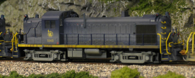
Photo of RS3
after painting:
As with any job, it's important
to have the right tools. So first, here is a list of the tools
you'll need:
Exacto knife with #11 and #17 blades
Micro-Mark Flexpad 320 grit or similar
Pin vise or finger drill with #58 drill bit
Flat head screwdriver 5/64"
Phillips screwdriver #0
Fine tip paint brush with wood handle (you'll see why later)
Cyanoacrylate Adhesive (CA)
Scotch Tape
And now a list of necessary parts and materials:
Pollyscale, "C&O Enchantment Blue"
Pollyscale, "Rust"
Pollyscale, "Concrete"
Pollyscale, "Earth"
Pollyscale, "Grimy Black"
Bethlehem Car Works RS3 Marker Lights, part #31 4pk.
Roundhouse Products #'s 2961 (red). 2962 (green) Marker Lamp Jewels
or MV Lenses (not sure of part #)
Evergreen Scale Models strip styrene #222, 1/16" rod
Kadee #5 couplers (Optional)
Details West AH-174 "Wabco" Single Chime Air Horn
Details West MU-266 MU Hose 3 cluster set
This is optional, but I feel is TOTALLY NECESSARY:
Spare RS3 shell to use as a mock-up to test fit parts BEFORE you scour or drill
out your
prized model!!
I'll assume the reader is unfamiliar with the anatomy of an Atlas RS3, so some
may find my
instructions a little wordy. I'm sorry in advance. Now let's get started!
Step 1a: Dissection
First, we'll remove the handrails. It's not necessary to remove the end
handrails above the
pilots, so we'll leave them alone. Carefully pull ends of rails out of the cab
and gently pull
rail stanchions up from steps leading to cab (both can be done carefully with
your fingers).
Then, take 5/64" flathead screwdriver and "pop" handrail stanchions out by
inserting
screwdriver tip up from beneath the walkways. Each stanchion has its own small
opening
where its base meets the walkways. You risk breaking them if you pull up with
your
fingers, so avoid doint that. The ends of the rails where they meet the end
steps can be
freed carefully by using the shaft of the screwdriver to pry them away. Use your
fingers as
"tweezers" if you need to, but be careful.
Once handrails are off, pinch the sides of the front and rear of the body near
the bottom
edge where it meets the walkways and lift to separate it from the chassis. Then,
take #0
screwdriver and remove draft gear boxes so the walkways can be removed from the
chassis.
Step 1b: If you are installing a decoder, now is a good time.
Step 2: Removing unneeded details
We'll do the easy one first. Each horn has two supports. We'll call them FRONT
(furthest
from the cab) and BACK (nearest to the cab). Take your Exacto knife with a #11
blade and
make a horizontal cut flush with the hood to separate the FRONT of the horn from
the
shell. We're going to use the existing hole closest to the cab on BOTH hoods, so
try not to
cut the horn completely off. If you're careful, the stem of the horn support
will stay in the
FRONT hole to act as a plug. Lift the horn off and discard. Put a spot of glue
on the plug
that remained in the FRONT hole to keep it from falling through the bottom.
Install new
horns in existing BACK holes using a touch of CA on the underside of the body.
We'll paint
them later.
Trim the edges of the MU hose castings and drill a hole for the correct mounting
location
on the pilots. They are marked R and L. When in place, paint hoses Grimy Black
and apply
silver paint to the ends.
Now this is where I hope you have a spare shell to practice this first. We have
to remove
the external "rib" on the right side of the long hood for the oil breather. The
CNJ units
didn't have this feature, instead they had a breather tube that didn't exit the
hood until it
neared the top. Take the Exacto knife with the #17 blade. This is a chisel tip
which you will
use as a planer to shave down the rib until it's flush with the hoodside. I turn
the blade so
the bevel is towards the body and work from top to bottom, removing small
portions at a
time. It's very possible for it to slip and get buried in your palm. How do I
know that? Once
you remove the majority of the rib, you can use the Flexpad to sand out any
imperfections.
Just for kicks, I also used the Flexpad to lightly sand the louvers on all the
doors to "bring
them out."
We'll make the breather tube out of the 1/16" styrene rod. Use the chisel tip
again to cut
the rod to a 1/2" length. Be sure you make a squared edge (it took me a couple
tries). You
can use the Flexpad to sand the ends to make them square if you can't get it
with the
blade. Height of this breather tube varied from one unit to the next, and some
even had a
bend in it to curve around the sloped side of the hood. I chose to take the easy
route and
glue the rod directly to the side of the hood. Use the scar where the rib was as
a guide. Put
a spot of CA on the shell nearer to the top and place the rod against the shell.
Check
photos to see where to align the bottom edge. I used the bottom edge of the
upper
louvers, but again, this varied. Hold it in place carefully until the glue sets.
Step 3: Marker Lights
This is another step in which it's important to have an extra shell. We're going
to use the
#58 drill to make mounting holes for the marker lights. The hole will be drilled
just to the
side of where the hood begins to slope and between the number board and small
line cast
in the plastic (one look and you'll know what I mean). The edge of the hole
should just
touch the inner edge of that line. Now, the #58 bit is too small for the marker
light
mounting pin, but this is good because the hole may need to be reamed in any
direction
to get the light's position correct. Once I got the hole correct, I test fitted
the light. When I
was happy, I trimmed the excess length of the mounting pin so it was just long
enough to
come through the shell. Put a drop of CA on the mounting pin and apply it to the
body.
Before the glue sets, it's possible to bend the light slightly to straighten it,
but be careful
because they're made of soft metal and you can snap one off. Trust me! When the
glue
sets, you can put another drop of CA on the underside just for good measure.
Wait until all
four corners are done to do this, then set the shell upside down so the glue
won't run
down and turn the shell into part of your workbench. Also, the weight of the
body keeps
pressure on the joints until they set.
Step 4: Prep and Paint
It's important that your model is free of grease or oil before you paint. I use
Pollyscale
Plastic Prep #546007. Apply with a cotton ball or paper towel generously to
shell and
running gear. DO NOT wash off! Instead, allow model to air dry. Break out the
C&O
Enchantment blue paint and the fine tipped brush. This color is so close to the
actual
color, I did not mix any other colors with it. You may find it a little light,
but the
application of a second coat will remedy that. Paint horns, breather, and marker
lamps.
Step 5: Jewel lenses
When the paint has dried, we can apply the jewel lenses. They are very small and
hard to
handle, but there's a trick to it. Go get that Scotch tape. First, doing one
lamp bezel at a
time, place a small drop of CA on one bezel (each lamp has two). Place a single
jewel
(colored side down) on a small piece of tape. Use the tape to hold the jewel as
you gently
place it over the bezel. The glue should hold the jewel as you take the tape
away. Now use
the opposite side of your paint brush (made of wood) to set the jewel in the
bezel. The
wood brush handle is not as prone to reacting with the glue as a plastic handle
and will
not take the jewel with it when you pull it away. Continue in this fashion, one
jewel at a
time.
Step 6a: Weathering
This is the point where you should do your weathering. If you are handy with an
airbrush,
you can reach amazing results on your running gear using only four colors: Grimy
Black,
Rust, Concrete and Earth (applied in that order). The body roof should get a
good coat of
Grimy Black, as well the topsides of the walkways and pilots. Some thinned Grimy
Black
can then be brushed onto the radiator and fan grills to darken them. Even in my
photos
from a distance, the radiator grills stand out nicely.
Step 6b: If you are installing a decoder in your model and were too excited to
begin the
detail work or were too lazy to do it in Step 1b, do it now.
Step 7: Assembly
Place walkways back over chassis and reattach draft gear boxes. Put on surgical
gloves, if
you have not had them on this whole time, to protect your model from greasy
fingerprints.
Snap body back onto the frame and reattach handrails. Use the 5/64" screwdriver
tip to
press stanchion bases back into respective holes.
I will add that my methods and techniques are only my own and that in no way do
I feel
they are correct or the preferred way to do things. I hope you all reached the
same
pleasing results with your models as I have with my own.
Happy modeling
Nick